
Glass Bottle Closures: Steam-Vacuum Lug, Continuous Thread and ROPP Capping Specs
Compare glass bottle closures across steam-vacuum lug, continuous thread (CT), and ROPP aluminum caps with torque, liner compression, and dud-detection specs.

Specifying glass bottle closures by nominal neck diameter alone causes three frequent bottling-line failures: lost headspace vacuum on hot-filled food jars, backed-off screw caps after 24-hour liner creep, and fractured pilfer-proof bridges or leaked spirits on roll-on aluminum shells. Matching the glass finish standard to the capper head mechanics before ordering bottling line equipment prevents thread stripping, gasket crush, and costly rework.
To specify glass bottle closures and capping stations without seal failures, lock four engineering parameters across container and closure drawings. First, pair quarter-turn tinplate or TFS lug caps (GPI 2000 to 2700 series, 38 to 82 mm, 3, 4, or 6 lugs) with a straight-line steam-vacuum capper (1.5 to 4.0 bar, 180 to 230 kg/h culinary steam sweep) that generates 12 to 22 inHg (40 to 75 kPa) cold vacuum and +1.5 to +4.5 mm positive lug security. Second, size continuous thread closures (GPI 400, 405, 410, 415, 425, 430) around a baseline application torque of T_app = 0.5 * D_mm (in-lb), accounting for 15% to 30% liner compression set so 24-hour removal torque (T_rem) stays within 40% to 70% of T_app under ASTM D2063, and add a post-cooling inline retorquer (80% to 90% of T_app) whenever polypropylene caps run on hot-fill lines. Third, calibrate 4-roller ROPP heads (GPI 1600, CETIE BVS 30x60 mm, MCA 28x18 mm) to 110 to 180 daN (250 to 400 lbf) overhead top load on 8011 or 3105 (H14/H16) aluminum shells to compress EPE or Saranex liners 20% to 35% and hold an 8 to 16 in-lb bridge-break torque. Fourth, verify 100% of sealed containers via non-destructive electromagnetic acoustic dud detection (>= 0.25 to 0.50 mm button concavity and > 200 to 400 Hz resonance shift rejection) and 360-degree camera vision (< 0.8 mm cap skew).
Use this engineering reference alongside the bottling-line guides overview to coordinate closure drawings with capping equipment selection, bottle neck finishes and closure compatibility, and inline bottle inspection systems.
Swipe or scroll horizontally to see all columns.
| Closure family | Glass finish standards | Common sizes & shell geometry | Shell & liner / gasket materials | Capping machine & head mechanics | Primary seal retention metric | Primary beverage & food applications |
|---|---|---|---|---|---|---|
| Quarter-Turn Lug (Twist-Off) Vacuum Closure | GPI 2000 to 2700 (2030, 2060, 2710); CETIE GME 20 series interrupted multi-start threads |
27 to 38 mm (3/4 lugs); 43 to 70 mm (4 lugs); 82 to 100 mm (6 lugs) |
0.15 to 0.22 mm tinplate or ECCS/TFS steel; flowed-in PVC plastisol or PVC-free TPE channel gasket (0.8 to 1.4 mm) |
Straight-line steam-vacuum belt capper (1.5 to 4.0 bar, 180 to 230 kg/h steam flush + quarter-turn cam/belts) |
12 to 22 inHg (40 to 75 kPa) cold vacuum; +2 to +6 mm lug pull-up; +1.5 to +4.5 mm security; >= 0.25 to 0.50 mm button deflection |
Hot-fill (82 to 95 deg C), pasteurized, and retorted (115 to 121 deg C) sauces, salsa, jams, pickles, baby food |
| Continuous Thread (CT) Screw Closure | GPI 400 (1.0 turn), 405 (1.5), 410 (1.5), 415 (2.0 tall), 425 (2.0 fine), 430 (buttress + bead) |
18 to 110 mm (20, 24, 28, 33, 38, 48, 53, 58, 63, 70, 89, 110 mm), 360 deg spiral thread |
Injection-molded PP, phenolic/urea thermoset, or tinplate/aluminum; F217 foamed PE, pulp/PVDC, PTFE, or foil induction liner | Inline 3/4-wheel spindle capper (100 to 250 bpm) or rotary magnetic/servo chuck turret (150 to 600+ bpm) with 15 to 45 lbf top spring |
T_app = 0.5 * D_mm (in-lb); 24-hour T_rem = 40% to 70% of T_app per ASTM D2063 after 15% to 30% liner compression set |
Syrups, condiments, spirits mixers, kombucha, wellness shots, pharmaceuticals, dry food jars |
| Roll-On Pilfer-Proof (ROPP) Aluminum Closure | GPI 1600 (1620, 1625, 1650, 1655); CETIE BVS 30x60 mm (EN 16293); MCA 28x18 mm (EN 15543); 31.5x24 mm |
18 to 38 mm (18, 22, 24, 28, 30, 31.5, 35, 38 mm) unthreaded cylindrical shell with perforated bridges |
8011 or 3105 aluminum alloy (H14 or H16 temper, 0.18 to 0.24 mm); EPE foam, Saranex (PVDC/PE), or tin-foil wadding (1.5 to 2.0 mm) |
Rotary or single-head 4-roller pressure-block ROPP head (110 to 180 daN top load, 2 thread rollers at 15 to 35 daN, 2 pilfer rollers at 12 to 28 daN) |
20% to 35% liner compression (0.4 to 0.7 mm height drop); 8 to 16 in-lb (0.9 to 1.8 N.m) bridge-break torque; up to 3.5 to 6.0 bar CO2 retention |
Distilled spirits, still and sparkling wines (BVS 30x60), extra-virgin olive oil (31.5x24), pharmaceutical syrups |
Matching glass bottle closures to GPI and CETIE neck finishes
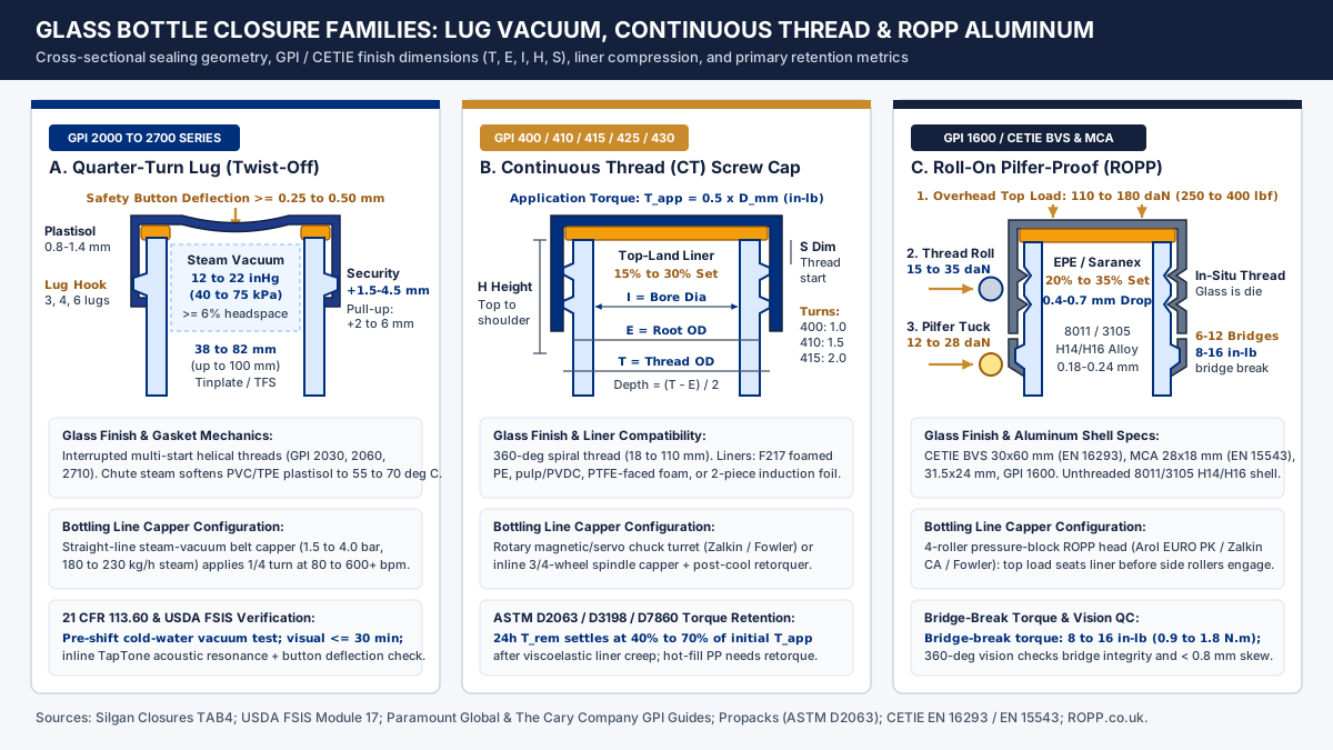
Unlike bar-top T-cork stoppers that seal by radial interference inside a smooth internal neck bore (18.5 mm or 19.5 mm I dimension, covered in our wholesale glass liquor bottles and bar-top bore specification guide), external glass bottle closures seal by clamping an elastomeric gasket or compressible liner against the top rim (sealing land) and upper shoulder of the glass finish. As documented in the GPI / SPI neck finish specification guide (paramountglobal.com) and The Cary Company guide to neck finishes and liner compatibility, five glass finish dimensions govern whether a closure seats without thread stripping or cocking:
Tdimension (thread crest outside diameter): The maximum outer diameter measured across the thread crests, which defines the nominal millimeter prefix in designations such as28-400or63-2030.Edimension (thread root wall outside diameter): The outer diameter of the cylindrical neck wall between or below the thread projections. Radial thread depth equals(T - E) / 2. If the closure thread root diameter exceedsTor undercutsEbeyond drawing tolerances, the cap strips under chuck torque or rocks sideways.Idimension (inner bore diameter): The minimum internal opening through the neck finish, which sets the clearance envelope for glass bottle filling machine nozzles, drip-control pourer fitments, and orifice reducers.Sdimension (thread start height): The vertical distance from the top sealing land to the upper leading edge of the first glass thread. Variations inSshift the angular final stop position of a lug or screw cap relative to top-land liner compression.Hdimension (total finish height): The vertical distance from the top sealing surface down to the transfer bead or shoulder intersection whereTextended downward contacts the container body. If the cap skirt depth exceedsH, the bottom edge of the closure bottoms out on the glass shoulder or transfer bead before the internal liner reaches its15% to 35%compression target, resulting in zero top-land seal pressure.
European and international glassmakers specify the same functional envelopes through CETIE finish data sheets (GME series), grouping vacuum twist-off finishes under the GME 20 series, continuous-thread finishes under the CT series, and roll-on metallic screw finishes under EN 16293 (BVS 30x60 mm deep wine and spirits finish) and EN 15543 (BVP and MCA 28 mm pressurized beverage finishes). Comparative machine studies from Cecle on screw cap, ROPP, and crimp capping compatibility and PMMI ProSource on commercial capping station integration confirm that each finish family requires a dedicated mechanical closing head.
Steam-vacuum lug capping for hot-fill sauces, salsas, and retorted jars
Quarter-turn twist-off lug closures dominate wide-mouth glass food jars and narrow-neck sauce and dressing bottling lines because interrupted multi-start helical glass threads (GPI 2000 to 2700 series) allow high-speed straight-line belt cappers to apply and seal metal caps without indexing rotary chucks. According to Tecnocap Group twist-off metal closure specifications and Silgan Closures Technical Assistance Bulletin TAB4 (Steel Closure Operating Guidelines), commercial twist-off shells are stamped from 0.15 to 0.22 mm electrolytic tinplate or electrolytic chromium-coated steel (ECCS / TFS) in diameters from 27 mm to 100 mm, with 3 or 4 inward-projecting lugs on 27 to 38 mm caps, 4 lugs on 43 to 70 mm caps (43, 48, 53, 58, 63, 66, 70 mm), and 6 lugs on 82, 89, and 100 mm wide-mouth caps.
Rather than relying on high rotational thread torque alone, a lug closure is a vacuum-assisted seal. Inside the cap perimeter sits a flowed-in annular channel gasket (0.8 to 1.4 mm thick) formulated from food-contact PVC plastisol or PVC-free thermoplastic elastomer (TPE) compliant with 21 CFR 177.1210. In a straight-line steam-vacuum capper, such as the systems documented in Silgan Closures TAB4 and the VTOPS MR5D30 linear steam-vacuum capping machine specification, filled glass containers pass beneath an enclosed stainless-steel steam hood supplied with 1.5 to 4.0 bar (0.15 to 0.40 MPa, consuming 180 to 230 kg/h of culinary steam). The steam tunnel performs two simultaneous mechanical actions before the lugs engage:
- Headspace air sweep and vapor condensation: Superheated steam flushes atmospheric air out of the container headspace (which must be maintained at
>= 6%of container overflow volume per USDA FSIS Thermal Processing Systems Module 17: Glass Container Closures). At100 deg Cand1 atm,1 gof liquid water occupies1,673 cm3of steam vapor; once the cap seals the jar mouth and the package cools to20 to 25 deg C, that trapped steam condenses into liquid water, generating12 to 22 inHg(40 to 75 kPa/300 to 560 mmHg) of internal vacuum (up to67 kPa/19.8 inHgon cold-fill vacuum cappers, and18 to 24 inHgwhen combined with82 to 93 deg Chot-fill thermal contraction). - Plastisol gasket softening: Low-pressure chute steam warms the cap’s plastisol compound to
55 to 70 deg Cjust before cap pick-off (without sterilizing the closure, as noted in Silgan TAB4) so the glass sealing rim sinks0.25 to 0.50 mminto the softened gasket as overhead sealer belts and quarter-turn cam bars rotate the cap1/4to1/6turn to hook the lugs beneath the inclined glass threads.
For thermally processed low-acid foods (pH > 4.6, water activity a_w > 0.85), federal regulations under 21 CFR 113.60(a) and (a)(2) mandate a recorded cold-water vacuum efficiency check of the steam capper before filling starts each shift, plus visual closure defect inspections at intervals not exceeding 30 minutes. Destructive teardown inspections described in USDA FSIS Module 17 track two physical position marks on the lug skirt: lug pull-up (distance from the glass vertical mold parting line to the leading edge of the cap lug, target +2 to +6 mm past the parting line) and security (how far the cap lug travels forward after removing the cap, breaking the vacuum, and re-applying the cap finger-tight until the gasket touches glass, target +1.5 to +4.5 mm or 1/16 to 3/16 in indicating real gasket compression).
Swipe or scroll horizontally to see all columns.
| Steam-vacuum lug parameter | 38 to 48 mm narrow-mouth lug cap |
53 to 70 mm standard jar lug cap |
82 to 100 mm wide-mouth lug cap |
Regulatory / OEM control basis |
|---|---|---|---|---|
| GPI finish series & lug count | GPI 2030 / 2060 (3 or 4 lugs) |
GPI 2030 / 2045 (4 lugs) |
GPI 2030 / 2710 (6 lugs) |
Silgan Closures TAB4; Tecnocap |
| Culinary steam supply & consumption | 1.5 to 3.5 bar (140 to 190 kg/h) |
2.0 to 4.0 bar (180 to 230 kg/h) |
2.5 to 4.0 bar (200 to 250 kg/h) |
VTOPS MR5D30; Silgan TAB4 |
| Plastisol gasket compound & rating | Standard PVC or TPE (82 to 95 deg C hot-fill / pasteurize) |
High-temperature PVC or PVC-free TPE (85 to 121 deg C pasteurize / retort) |
Retort-grade plastisol (115 to 121 deg C overpressure retort) |
21 CFR 177.1210; Tecnocap |
| Minimum headspace & cold vacuum | >= 6% overflow volume; 12 to 20 inHg (40 to 67 kPa) |
>= 6% overflow volume; 14 to 22 inHg (47 to 75 kPa) |
>= 6% to 8% overflow volume; 12 to 20 inHg (40 to 67 kPa) |
USDA FSIS Module 17 |
| Lug pull-up, security & QC frequency | Pull-up +2 to +5 mm; security +1.5 to +3.5 mm; pre-shift cold-water vacuum test |
Pull-up +2 to +6 mm; security +1.5 to +4.5 mm; visual check <= 30 min |
Pull-up +3 to +6 mm; security +2.0 to +4.8 mm; teardown every 4 hours |
21 CFR 113.60(a)(2); USDA FSIS |
Continuous thread closures: application torque, liner compression, and 24-hour relaxation
Continuous thread closures (CT caps) engage a single uninterrupted 360 deg spiral glass thread specified by a two-part GPI/SPI code (nominal diameter T in mm followed by a three-digit thread-turn style). As defined in the GPI/SPI thread classification guide (paramountglobal.com), the six industrial CT thread styles are:
GPI 400:1.0full thread turn; universal standard for wide-mouth jars (48-400to89-400) and general liquid bottles (18-400to38-400).GPI 405:1.5thread turns for depressed-thread closures.GPI 410:1.5thread turns with a medium-height neck and deeper cap skirt that conceals the glass thread on syrups, sauces, and personal-care bottles (20-410,24-410,28-410).GPI 415:2.0thread turns with a tall, narrow neck profile used for pourable dressings, cocktail mixers, and pharmaceutical liquids (24-415,28-415,33-415).GPI 425:2.0closely spaced fine-pitch turns engineered for small8 to 15 mmvials and dropper assemblies.GPI 430: Heavy buttress thread profile with a lower glass retaining bead designed for snap-in pour spouts, corrosive reagents, and high-torque child-resistant closures (28-430,38-430).
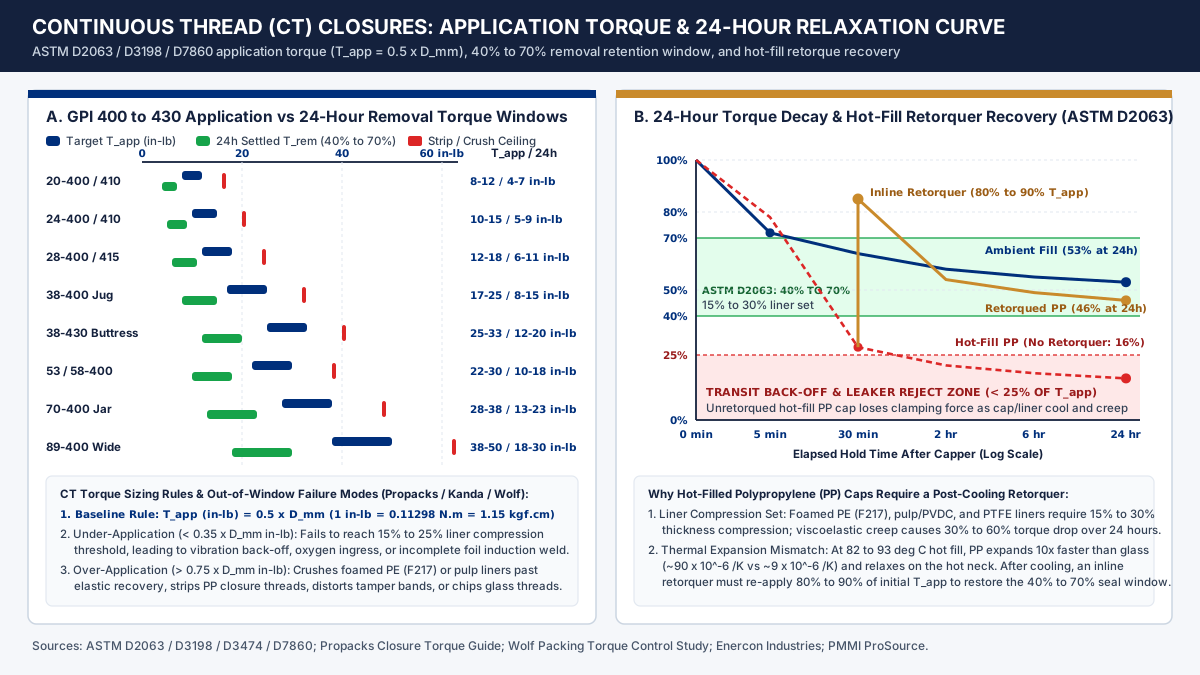
On the packaging line, CT closures are applied either by inline 3- or 4-wheel spindle cappers (100 to 250 bpm) or by high-speed rotary magnetic-clutch and closed-loop servo chuck turrets (150 to 600+ bpm), such as those built by Fowler Products (ProMach / Zalkin Americas). According to Propacks closure torque testing guidelines (ASTM D2063 / D3474 / D7860), Kanda Cork Closures screw cap torque specifications, and the Wolf Packing capping machine torque control study, initial application torque (T_app, in in-lb, where 1 in-lb = 0.11298 N.m = 1.15 kgf.cm) scales with closure nominal diameter (D_mm) according to the baseline engineering rule:
T_app (in-lb) = 0.5 * D_mm
Applying T_app drives the pre-threaded cap downward along the inclined glass thread helix to compress the internal disc liner (F217 three-ply low-density foamed polyethylene, pulpboard/PVDC, expanded PTFE, or a two-piece aluminum foil induction liner) against the glass top sealing land:
Liner Compression Set (%) = [(t_0 - t_compressed) / t_0] * 100
To establish a hermetic liquid and gas barrier without crushing the foam cells, liner compression must land between 15% and 30% of uncompressed liner thickness (t_0 = 0.8 to 1.5 mm). If application torque drops below 0.35 * D_mm (in-lb), liner compression falls short of 15% and permits transit vibration back-off or incomplete electromagnetic foil weld during Enercon induction cap sealing. Conversely, if application torque exceeds 0.75 * D_mm (in-lb), the chuck crushes F217 or pulp liners beyond elastic recovery, strips polypropylene (PP) closure threads, distorts tamper-evident drop bands, or chips the glass finish.
Why 24-hour removal torque drops to 40% to 70% and why hot-fill PP caps require an inline retorquer
Immediately after the capper chuck releases the container, viscoelastic compression creep inside the polymer liner and stress relaxation across the cap skirt reduce the clamping force on the glass thread flanks. Under ASTM D2063 (Torque Retention for Packages with Continuous Thread Closures), ASTM D3198, and ASTM D7860, quality teams measure both immediate removal torque (T_rem_5min, tested within 5 minutes of capping to verify chuck consistency) and 24-hour settled removal torque (T_rem_24h):
R_24h (%) = (T_rem_24h / T_app) * 100
Across ambient-filled glass containers with F217 foamed PE, pulp/PVDC, or induction liners, R_24h stabilizes inside a 40% to 70% retention window (40% to 60% for standard foamed PE and pulp liners). However, when a hot-filled sauce or beverage (82 to 93 deg C) is capped with an injection-molded polypropylene (PP) CT closure, a severe thermal expansion mismatch occurs. Polypropylene exhibits a coefficient of linear thermal expansion (alpha_PP ~ 90 * 10^-6 /K) roughly ten times higher than soda-lime container glass (alpha_glass ~ 9 * 10^-6 /K). Heat conducted from the 88 deg C bottle neck expands the PP cap skirt and accelerates polymer creep while the package traverses the hold and cooling tunnel. Once the bottle cools to 25 deg C, residual removal torque on an unretorqued PP cap frequently drops below 20% to 25% of T_app (into the transit leaker zone). As documented by PMMI ProSource, hot-fill lines running plastic CT closures must install a downstream inline spindle retorquer after the cooling tunnel and air-knife dryer to re-apply 80% to 90% of initial T_app, restoring 24-hour removal torque to the 40% to 70% target window.
Swipe or scroll horizontally to see all columns.
| GPI CT finish designation | Nominal thread OD (T) |
Recommended application torque (T_app) |
Immediate removal torque (5 min) |
Settled 24-hour removal torque (40% to 70%) |
Liner crush / thread strip ceiling |
|---|---|---|---|---|---|
20-400 / 20-410 |
20.0 mm |
8 to 12 in-lb (0.90 to 1.36 N.m) |
6 to 9 in-lb (0.68 to 1.02 N.m) |
4 to 7 in-lb (0.45 to 0.79 N.m) |
> 16 in-lb (1.81 N.m) |
24-400 / 24-410 |
24.0 mm |
10 to 15 in-lb (1.13 to 1.69 N.m) |
7 to 11 in-lb (0.79 to 1.24 N.m) |
5 to 9 in-lb (0.56 to 1.02 N.m) |
> 20 in-lb (2.26 N.m) |
28-400 / 28-410 / 28-415 |
28.0 mm |
12 to 18 in-lb (1.36 to 2.03 N.m) |
9 to 14 in-lb (1.02 to 1.58 N.m) |
6 to 11 in-lb (0.68 to 1.24 N.m) |
> 24 in-lb (2.71 N.m) |
38-400 (Standard Syrup / Jug) |
38.0 mm |
17 to 25 in-lb (1.92 to 2.82 N.m) |
12 to 19 in-lb (1.36 to 2.15 N.m) |
8 to 15 in-lb (0.90 to 1.69 N.m) |
> 32 in-lb (3.62 N.m) |
38-430 (Buttress Pour-Spout) |
38.0 mm |
25 to 33 in-lb (2.82 to 3.73 N.m) |
18 to 25 in-lb (2.03 to 2.82 N.m) |
12 to 20 in-lb (1.36 to 2.26 N.m) |
> 40 in-lb (4.52 N.m) |
53-400 / 58-400 (Medium Jar) |
53.0 to 58.0 mm |
22 to 30 in-lb (2.49 to 3.39 N.m) |
16 to 23 in-lb (1.81 to 2.60 N.m) |
10 to 18 in-lb (1.13 to 2.03 N.m) |
> 38 in-lb (4.29 N.m) |
70-400 / 70-450 (Wide-Mouth Jar) |
70.0 mm |
28 to 38 in-lb (3.16 to 4.29 N.m) |
20 to 28 in-lb (2.26 to 3.16 N.m) |
13 to 23 in-lb (1.47 to 2.60 N.m) |
> 48 in-lb (5.42 N.m) |
89-400 (Bulk Wide-Mouth Jar) |
89.0 mm |
38 to 50 in-lb (4.29 to 5.65 N.m) |
27 to 38 in-lb (3.05 to 4.29 N.m) |
18 to 30 in-lb (2.03 to 3.39 N.m) |
> 62 in-lb (7.00 N.m) |
ROPP aluminum closures: 4-roller head kinematics, top load, and bridge-break torque
A Roll-On Pilfer-Proof (ROPP) closure arrives at the bottling line as a smooth, unthreaded cylindrical aluminum shell fitted with a top liner disc (expanded polyethylene EPE, Saranex PVDC/PE, or Saran-tin foil wadding for fine wine bottling lines) and a perforated lower tamper-evident skirt connected by 6 to 12 narrow metal bridges. As detailed in the ROPP Capping Guide (ropp.co.uk) and CETIE GME finish standards, the glass bottle neck itself functions as the forming mandrel under standards such as CETIE BVS 30x60 mm (EN 16293 for still wine and spirits), MCA 28x18 mm / BVP (EN 15543 for carbonated and still beverages), 31.5x24 mm (for extra-virgin olive oil and spirits with non-refillable pourer fitments), and North American GPI 1600 (1620, 1625, 1650, 1655) series finishes.
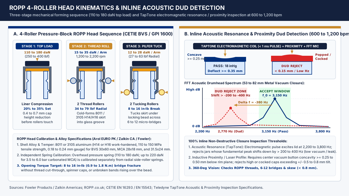
To cold-form the metal cleanly without spring-back or fracture, ROPP shells are deep-drawn from 8011 or 3105 aluminum alloy in H14 or H16 work-hardened temper (110 to 150 MPa ultimate tensile strength, 3% to 6% elongation, 0.18 to 0.24 mm sheet thickness). On commercial 4-roller mechanical pressure-block ROPP heads (such as Zalkin CA and Arol EURO PK class heads integrated by Fowler Products), the spinning head (1,200 to 2,200 rpm) executes a strictly timed three-stage mechanical sequence:
- Stage 1 (Overhead pressure-block seating and liner compression): Before any side roller touches the aluminum wall, a central spring-loaded or pneumatic pressure block presses vertically downward on the cap top at
110 to 180 daN(250 to 400 lbf/112 to 184 kgf, or up to180 to 220 daNfor3.5 to 6.0 barsparkling wine and carbonated MCA finishes). This axial load draws the top corner radius tight around the glass sealing surface and compresses the1.6 to 2.0 mmEPE or Saranex liner by20% to 35%, producing a measurable cap height drop of0.4 to 0.7 mm. Because top-load compression occurs before thread rolling, the threads locked into the skirt in Stage 2 hold that compressed liner position permanently after the head lifts. - Stage 2 (Radial thread-forming rollers): Two opposing cam-driven arms carrying profiled steel or titanium-nitride-coated thread rollers advance radially inward with
15 to 35 daN(34 to 79 lbf) of spring force per roller arm, rolling the ductile0.20 mmaluminum wall directly into the glass thread grooves. - Stage 3 (Pilfer-proof tucking rollers): Two opposing lower arms carrying narrower tucking rollers advance radially inward with
12 to 28 daN(27 to 63 lbf) of spring force per arm, rolling the bottom edge of the perforated skirt inward beneath the glass locking bead (transfer bead). When the consumer first unscrews the cap, the tucked lower band catches against the glass locking bead so the6 to 12micro-bridges fracture cleanly at a first-opening removal torque of8 to 16 in-lb(0.9 to 1.8 N.m).
During bottling-line format changeovers, operators must calibrate overhead pressure springs independently from side-roller springs and check glass finish wall thickness uniformity (+/- 0.25 mm), as emphasized in Cecle’s ROPP roller calibration analysis.
Swipe or scroll horizontally to see all columns.
| ROPP head stage / parameter | Mechanical force / calibration window | Resulting package dimension / metric | Under-calibration failure mode | Over-calibration failure mode |
|---|---|---|---|---|
Stage 1: Overhead Pressure Block (Top Load) |
110 to 180 daN (250 to 400 lbf); 180 to 220 daN for high-CO2 MCA |
20% to 35% EPE/Saranex liner compression; 0.4 to 0.7 mm cap height drop |
< 100 daN: < 15% liner compression, oxygen ingress, liquid weeping, or “spinner” cap |
> 220 daN: liner extrusion, crushed glass sealing land, or buckled bottle neck |
Stage 2: Thread-Forming Rollers (2 Upper Arms) |
15 to 35 daN (34 to 79 lbf) radial spring load per arm at 1,200 to 2,200 rpm |
Full aluminum conformity to glass thread root (E dia); removal torque 8 to 16 in-lb |
< 12 daN: shallow thread depth, cap strips over glass thread on opening or blow-off under CO2 |
> 40 daN: aluminum wall “cut-through” at thread crest, high opening torque (> 20 in-lb), chipped thread |
Stage 3: Pilfer-Proof Tucking Rollers (2 Lower Arms) |
12 to 28 daN (27 to 63 lbf) radial spring load per arm |
Skirt tucked tightly beneath locking bead; 6 to 12 intact bridges fracture on opening |
< 10 daN: loose tuck (” flared skirt”); tamper band slides intact over glass bead without breaking bridges |
> 32 daN: premature bridge fracture during capping (“broken bridges on line”) or scored glass bead |
Inline acoustic dud detection and vision closure inspection on bottling lines
Destructive torque and vacuum gauge tests sample only a fraction of shift production. To prevent a single unsealed jar or cross-threaded bottle from reaching the case packer, commercial bottling line equipment integrates 100% non-destructive inline closure inspection downstream of the capper and cooling tunnel, as detailed in Teledyne TapTone acoustic and proximity inspection documentation and our bottle inspection systems guide. When preparing a bottling equipment RFQ checklist, specify three complementary inline inspection gates:
- Electromagnetic impulse acoustic resonance dud detection: As capped jars or bottles pass beneath an overhead sensor bridge at speeds up to
600 to 1,200 bpm, a non-contact inductive coil fires a< 1 mselectromagnetic pulse into the conductive steel lug cap or aluminum closure. That eddy-current impulse flexes the center of the metal lid like a taut drumhead. A directional microphone captures the resulting acoustic vibration and runs a Fast Fourier Transform (FFT) to calculate the fundamental resonance frequency (f_0) and decay envelope. A hermetically sealed lug jar holding12 to 22 inHgof internal vacuum exhibits high membrane tension and a sharp acoustic peak between2,200 and 3,800 Hz(depending on cap diameter53 to 82 mm). Any jar with low vacuum or a micro-leak exhibits lower membrane tension, shiftingf_0downward by> 200 to 400 Hzwith damped amplitude and firing a high-speed pneumatic reject pusher. - Inductive proximity and laser safety-button deflection gauging: Paired with the acoustic coil, dual or triple eddy-current proximity probes (or laser triangulation profilers) scan across the closure centerline along the conveyor axis. By comparing the height of the outer cap rim against the center flip-panel vacuum button, the sensor verifies that the center button is pulled down
>= 0.25 to 0.50 mm(0.010 to 0.020 in) below the rim plane after cooling (as required by post-cooling button checks in Silgan TAB4), while rejecting cocked or high caps whose rim-to-rim tilt exceeds+/- 0.5 to 0.8 mm. - 360-degree high-speed vision closure and bridge inspection: Immediately after rotary CT or ROPP cappers, a multi-camera LED strobe vision tunnel photographs the bottle neck from
4 to 6radial angles. Machine-vision algorithms reject cocked caps (> 0.8 mmskew), high caps (> 1.0 mmabove nominal seated height), shallow ROPP thread impressions, split or untucked pilfer bands, and pre-broken tamper bridges.
Swipe or scroll horizontally to see all columns.
| Inline inspection gate | Sensing principle | Target closure families | Quantitative pass / reject threshold | Line speed rating |
|---|---|---|---|---|
| Electromagnetic Acoustic Dud Detector (TapTone) | < 1 ms inductive pulse excites lid drumhead mode; FFT microphone measures resonance f_0 (Hz) |
Steel twist-off lug caps (38 to 100 mm), PT caps, aluminum ROPP |
Pass: sharp peak inside 2,200 to 3,800 Hz recipe window; Reject: f_0 shifts down by > 200 to 400 Hz (< 8 to 10 inHg vacuum) |
150 to 1,200+ bpm |
| Eddy-Current Proximity / Laser Lid Profiler | Differential height scan across cap outer rim and depressed center vacuum button | Vacuum safety-button lug caps, metal CT caps, ROPP shells | Pass: center button concavity >= 0.25 to 0.50 mm below rim; Reject: button < 0.15 mm or rim tilt > +/- 0.5 to 0.8 mm |
150 to 1,200+ bpm |
| 360-Degree Multi-Camera Vision Inspector | Strobe LED optical imaging (4 to 6 cameras) around finish, cap skirt, and neck fill level |
ROPP aluminum (BVS / MCA / GPI 1600), plastic & metal CT, bar-top corks |
Pass: cap skew < 0.8 mm, 6 to 12 intact ROPP bridges, fill height +/- 1.5 to 2.5 mm; Reject: broken bridge, untucked bead, cocked cap |
100 to 800+ bpm |
Frequently asked questions
How do I choose between a twist-off lug cap, a continuous thread cap, and an ROPP aluminum closure?
Match the closure family to your thermal filling process and glass finish standard. Use quarter-turn tinplate or TFS twist-off lug caps (GPI 2000 to 2700 series, 38 to 82 mm) on straight-line steam-vacuum cappers when hot-filling, pasteurizing, or retorting food jars and sauces that require 12 to 22 inHg of internal headspace vacuum. Use pre-threaded continuous thread (CT) closures (GPI 400 to 430 series) on spindle or rotary chuck cappers for ambient syrups, condiments, wellness shots, and personal-care bottles sealed by 15% to 30% top-land liner compression or foil induction welding. Use unthreaded 8011 or 3105 aluminum Roll-On Pilfer-Proof (ROPP) closures (CETIE BVS 30x60 mm, MCA 28x18 mm, GPI 1600) on 4-roller pressure-block heads for distilled spirits, wine, and olive oil requiring integral metal bridge tamper evidence.
What is the rule of thumb for continuous thread application torque and 24-hour removal torque?
Set baseline continuous thread application torque (T_app, in in-lb) to approximately 0.5 times the closure’s nominal millimeter diameter (T_app = 0.5 * D_mm, such as 12 to 18 in-lb for a 28-400 cap and 17 to 25 in-lb for a 38-400 cap). Because polymer foam (F217) and pulp liners undergo viscoelastic compression creep after capping, 24-hour settled removal torque (T_rem) measured under ASTM D2063 relaxes to 40% to 70% (40% to 60% for standard foam/pulp liners) of the initial application torque.
Why do hot-filled glass bottles with polypropylene screw caps need a downstream retorquer?
Polypropylene (PP) has a linear thermal expansion coefficient (~90 * 10^-6 /K) roughly ten times higher than soda-lime glass (~9 * 10^-6 /K). When a PP continuous thread cap is torqued onto a hot-filled glass bottle (82 to 93 deg C), heat from the glass neck expands the plastic cap skirt and accelerates liner stress relaxation. As the bottle cools through the cooling tunnel, the cap loses clamping tension and 24-hour removal torque can fall below 25% of T_app; installing an inline spindle retorquer after cooling re-applies 80% to 90% of initial torque to restore a hermetic seal.
How does an inline acoustic dud detector identify low-vacuum glass jars without touching the cap?
An inline electromagnetic acoustic dud detector (such as Teledyne TapTone) fires a < 1 ms inductive pulse into the passing steel or aluminum closure, flexing the center panel like a drumhead without physical contact. A microphone and Fast Fourier Transform (FFT) analyzer measure the lid’s fundamental acoustic resonance frequency (typically 2,200 to 3,800 Hz on a 12 to 22 inHg vacuum jar) while proximity probes measure center button concavity (>= 0.25 to 0.50 mm), automatically rejecting any jar whose frequency shifts downward by > 200 to 400 Hz or whose button sits flat.
Method and sources
This specification guide synthesizes closure finish dimensions, steam-vacuum operating parameters, torque retention equations, ROPP roller force windows, and inline inspection thresholds from regulatory standards, technical bulletins, and equipment engineering references accessed in October 2026:
- Silgan Closures (White Cap), Technical Assistance Bulletin TAB4: Steel Closure Operating Guidelines (Revision B): GPI 2000 to 2700 twist-off steel closure mechanics, straight-line steam-vacuum headspace sweeping, plastisol gasket softening,
>= 6%headspace rule, and post-cooling vacuum button verification. - 21 CFR 113.60, Containers (Thermally Processed Low-Acid Foods Packaged in Hermetically Sealed Containers), Cornell Law School Legal Information Institute (eCFR Title 21): mandatory
<= 30 minutevisual closure defect checks and pre-shift cold-water vacuum efficiency testing for vacuum-sealed glass jars under21 CFR 113.60(a)(2). - USDA Food Safety and Inspection Service (FSIS), Thermal Processing Systems (TPSP) Student Guide, Module 17: Glass Container Closures: engineering comparison of Lug, Continuous Thread (CT), and Press-On Twist-Off (PT) closures, vacuum formation variables, and destructive teardown metrics (vacuum, removal torque, lug pull-up, and security).
- Tecnocap Group, Twist-Off Metal Closures for Glass Food Jars and Bottles and VTOPS, Steam Vacuum Capping Machine Series for Glass Jars (MR5D30):
38 to 100 mmtinplate/TFS lug closure diameters, pasteurization and retort plastisol compounds,<= 0.4 MPa(4.0 bar) steam supply,180 to 230 kg/hsteam consumption, and67 kPa(19.8 inHg) vacuum performance. - GPI / SPI Bottle Neck Finishes, Thread Sizes & Dimensions Guide (paramountglobal.com) and The Cary Company, Guide to Neck Finishes: GPI Designations, Lug Finishes, and Liner Compatibility: definitions of
T,E,I,H, andSfinish dimensions,GPI 400 / 405 / 410 / 415 / 425 / 430thread-turn classifications, and liner selection (F217foamed PE, pulp/PVDC, PTFE, plastisol, and induction foil). - Propacks, Closure Torque Guide: How to Set, Test, and Control Screw Caps (ASTM D2063 / D3474 / D7860), Kanda Cork Closures, Screw Cap Torque Guide for Leak-Proof Bottle Closures, Wolf Packing, Capping Machine Torque Control Study, and Enercon Industries, Understanding Application and Removal Torque:
T_app = 0.5 * D_mmsizing rule,40% to 70%24-hour removal torque retention window, liner compression set limits, and immediate vs 24-hour torque testing protocols. - ROPP.co.uk, ROPP Capping Guide: Roll-On Pilfer-Proof Aluminum Closure Mechanics and CETIE, Glass Finish Data Sheets (GME): BVS (EN 16293), BVP / MCA (EN 15543), and Vacuum Lug Standards: three-stage ROPP roller forming sequence,
8011 / 3105(H14 / H16) aluminum shell specifications, and international finish standards. - Fowler Products (ProMach / Zalkin Americas), Rotary Chuck and ROPP Capping Turrets, Cecle, Screw Cap vs ROPP vs Crimp Capping Compatibility & Cost, and PMMI ProSource, Sealing the Deal: How Capping Machines Protect Your Product:
110 to 180 daN(250 to 400 lbf) 4-roller ROPP overhead top-load calibration, rotary magnetic/servo chuck turrets, and post-cooling inline retorquers. - Teledyne TapTone, Acoustic, Proximity, and Mechanical Vacuum & Leak Inspection Systems: non-destructive electromagnetic impulse acoustic resonance dud detection (
f_0FFT analysis) and eddy-current proximity button deflection inspection at speeds up to1,200+ bpm.
Related guides
Choosing Capping Equipment for Glass Bottles and Jars
Prepare a capping requirement from finish and closure data: screw, ROPP, crown, lug, press-on and cork application, torque, and how to verify closures.
Read the guide
Bottle Neck Finishes and Closure Compatibility
How to read finish designations such as 28-400 and the T, E, I, H and S dimensions, and why a matching nominal diameter does not prove a closure fits.
Read the guide
Bottle Inspection Systems: Comparing What Each System Checks
Compare empty bottle, fill level, closure, label and code inspection by scope and limits, and ask for reject verification, test bottles and validation records.
Read the guide